The InFlux project provides complementary real-world benchmarking and synthetic training data for dynamic camera intrinsics estimation.
InFlux-Real is the unified real-world benchmark for evaluating per-frame camera intrinsics estimation on videos with dynamic intrinsics. It is constructed by calibrating metadata-enabled cinema zoom lenses across their zoom and focus ranges, then using per-frame lens metadata and lens-specific lookup tables to recover ground truth intrinsics for benchmark footage.
InFlux++ Synth is a large-scale synthetic training dataset for training and finetuning dynamic intrinsics prediction models. It uses procedural scene generation and virtual cameras with smoothly changing zoom, focus, and pose, providing exact per-frame ground truth from the renderer.
InFlux and InFlux++ Real obtain ground truth camera intrinsics for videos with dynamic intrinsics using the same core methodology. The cinema zoom lenses used for benchmark capture record per-frame lens metadata consisting of LFL and FD. For each lens, we perform calibration over a grid of LFL and FD settings and use the resulting measurements to construct a lens-specific lookup table (LUT). During benchmark capture, each frame's recorded LFL and FD are used to query the corresponding LUT and recover its ground truth camera intrinsics.
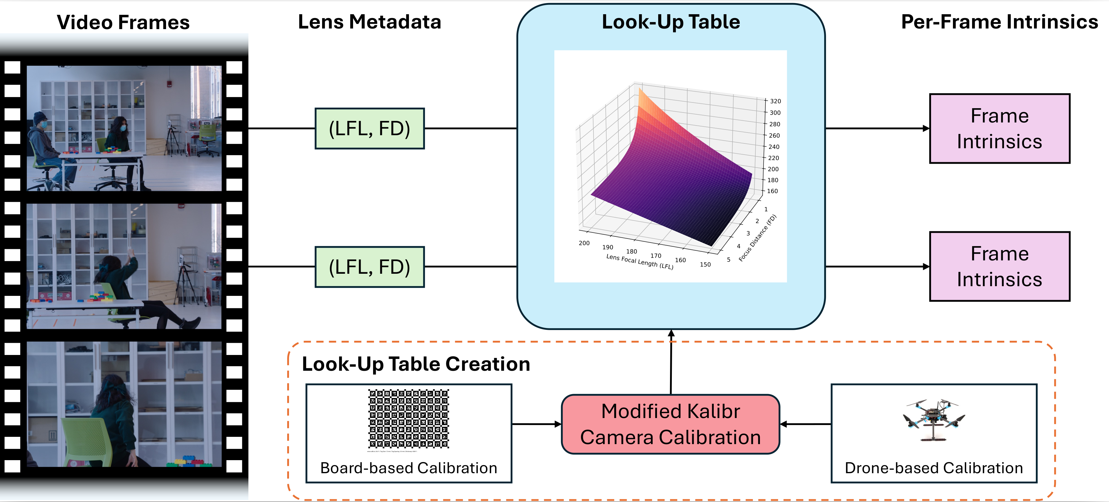
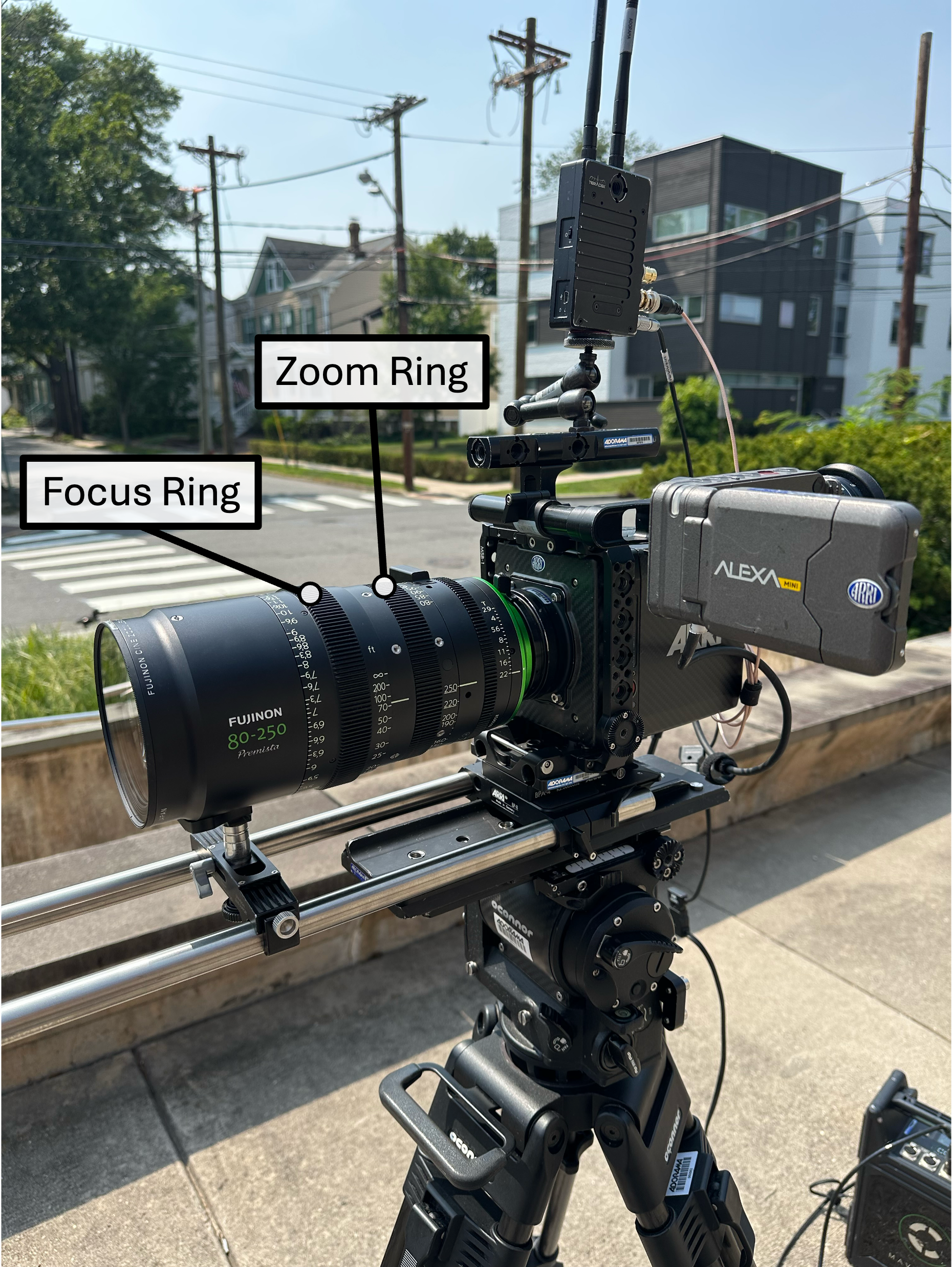
We use an ARRI Alexa Mini with two PL-mount cinema zoom lenses: the Canon CINE-SERVO 17-120 mm and the Fujinon Premista 80-250 mm. These lenses record /i Technology metadata, including LFL and FD, for every frame. We extract the recorded metadata with ARRI Reference Tool version 0.3.0. For a fixed lens and sensor combination, the pair (LFL, FD) uniquely identifies the lens's optical state. Note that LFL is not equivalent to CFL, so LFL cannot be inserted directly into the intrinsics matrix and must be used to query the calibrated LUT instead.
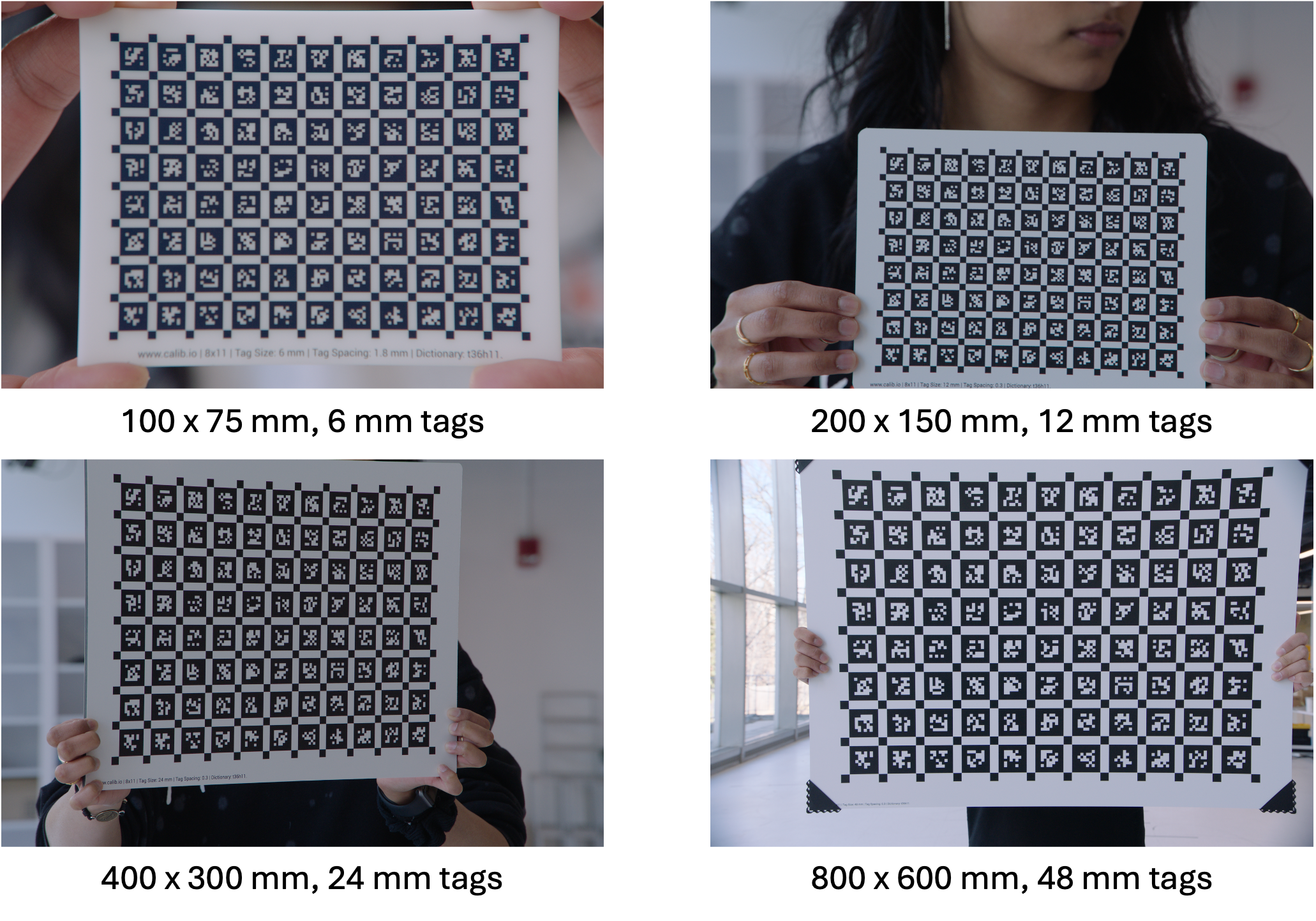
Camera calibration depends on accurate 2D detections of a target with known 3D structure. For each experiment, the target must be placed at the selected FD so that it appears sharp, occupies a large portion of the image to improve detection precision, and is captured across the camera field of view (FOV) to obtain accurate calibration of camera distortion. These constraints mean that the appropriate target size must scale with the size of the FOV spatial footprint (FSF), defined as the 3D region within the camera FOV around the selected FD that remains in focus. Because FSF size varies substantially with LFL and FD, no single physical board remains both large and clearly detectable across all experiments while supporting full FOV coverage.
Both InFlux and InFlux++ Real use the following four physical 8 × 11 AprilGrid board sizes with a tag spacing ratio of 0.3 for small and medium FSFs:
For each experiment, we select the largest board whose full pattern fits within the camera FOV when placed at the selected FD. We then record calibration images by moving the board throughout the FSF and activating multiple axes of rotation, following standard calibration practice.
For large FSFs, a target that remains in focus and prominent in the image can become impractical to move around. InFlux and InFlux++ Real use two alternative calibration strategies to overcome this challenge.
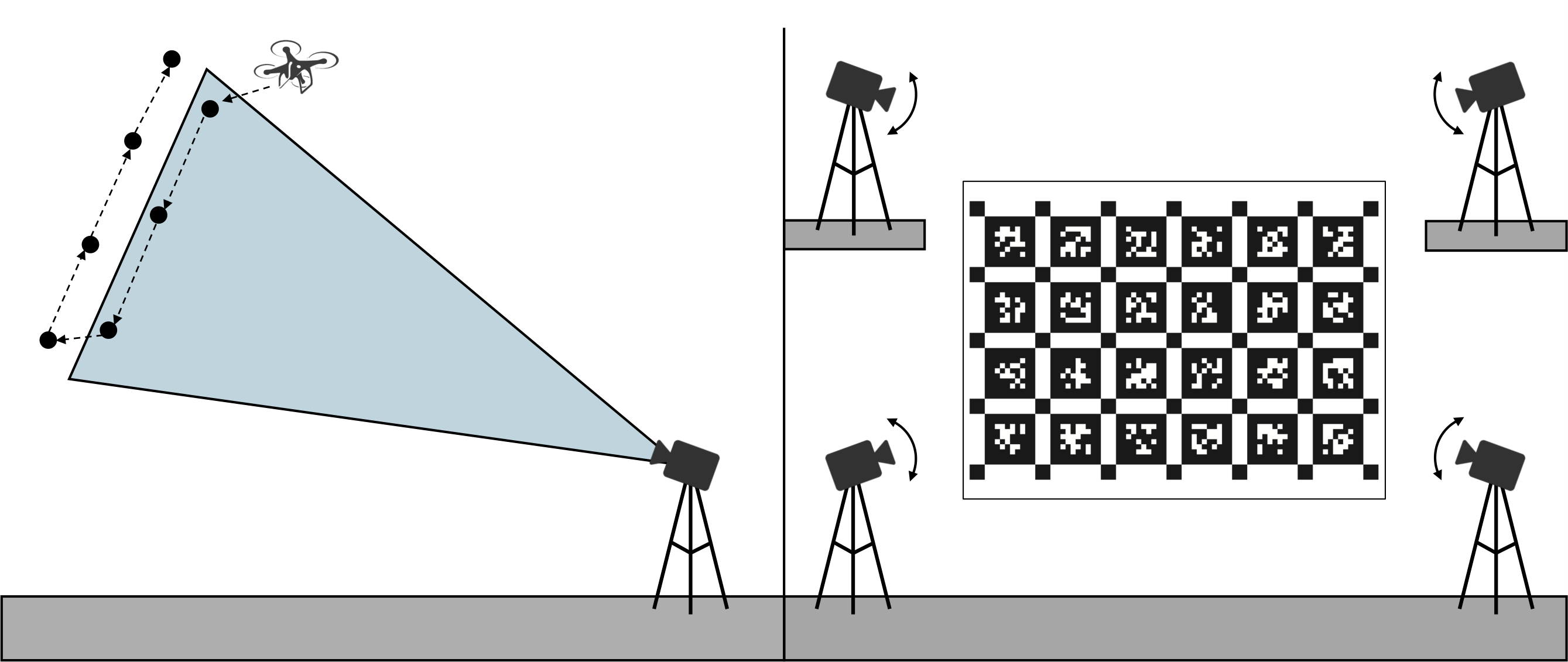
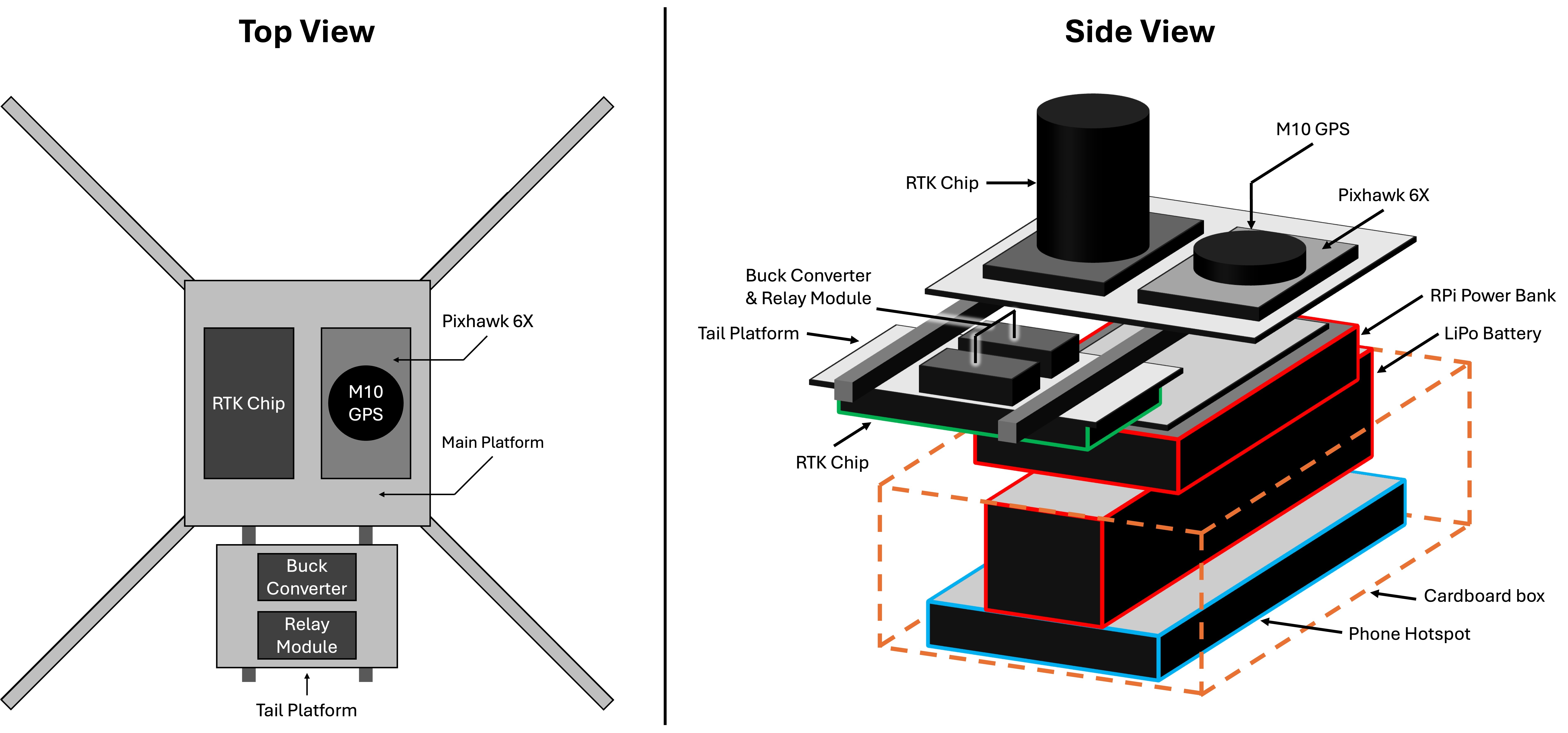
InFlux uses a Holybro X500 V2 drone as a mobile calibration target to establish the 2D–3D correspondences required for camera calibration. A Septentrio Mosaic X5 real-time kinematic (RTK) receiver provides the target's 3D position, while a Raspberry Pi 4 Model B triggers a visible LED used to locate the target in the image. With the camera fixed, the drone visits a 4 × 3 × 2 grid of locations throughout the FSF. The released InFlux extension of Kalibr supports calibration from this custom set of 2D–3D correspondences rather than requiring planar-board observations.
For large FSFs, the board-based calibration strategy of holding the camera stationary while moving the calibration board through the camera's FSF becomes difficult to execute, because the larger boards needed to remain prominent in the image are harder to maneuver and require more open space. Successful camera calibration, however, does not require the camera itself to remain stationary. It only requires the relative pose between the camera and target to vary so that the target is observed across the camera FOV and at diverse orientations. InFlux++ Real therefore keeps the large target fixed and moves the camera around it. Camera translation, pan, and tilt change where the target appears in the image and excite multiple axes of rotation, making board-based calibration practical again for large FSFs when a sufficiently large rigid display surface is available.
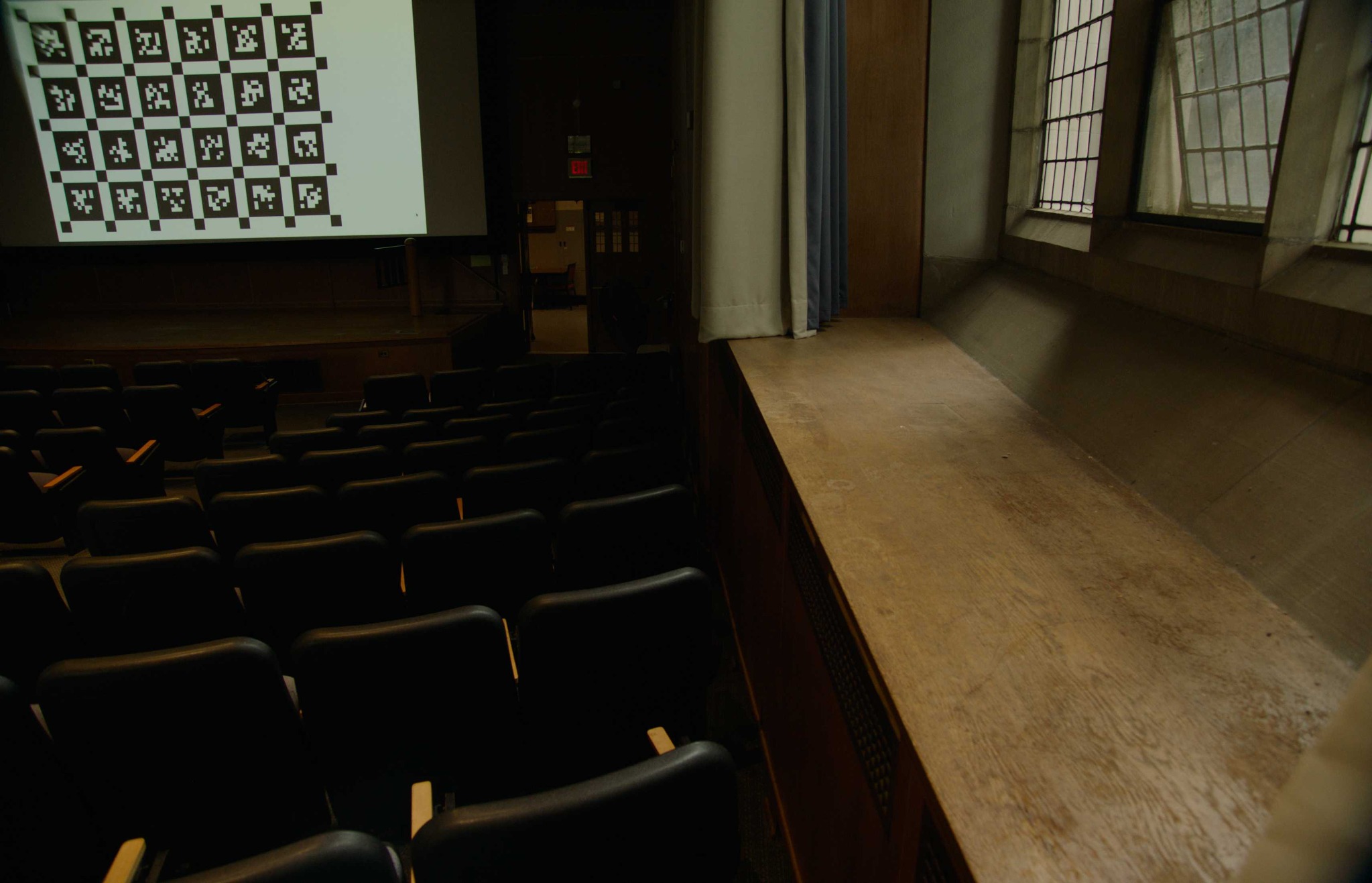
For large FSF calibration, InFlux++ Real adds a 4 × 5 grid of 96 mm tags, an 8 × 11 grid of 192 mm tags, and a 4 × 6 grid of 384 mm tags. The 96 mm pattern is printed as a sticker and attached to a flat 800 mm × 600 mm board, which is moved through the FSF relative to a fixed camera position. The 192 mm and 384 mm patterns are projected onto a 5.45 m × 3.06 m rigid screen in a multi-story lecture hall. For these projected patterns, we keep the screen fixed and move the camera between left and right positions on both the ground floor and balcony. At each position, we pan and tilt the camera so that the target appears at different image locations and orientations, providing FOV coverage and exciting multiple axes of rotation. For each experiment, we select the largest pattern that fits within the camera FOV.
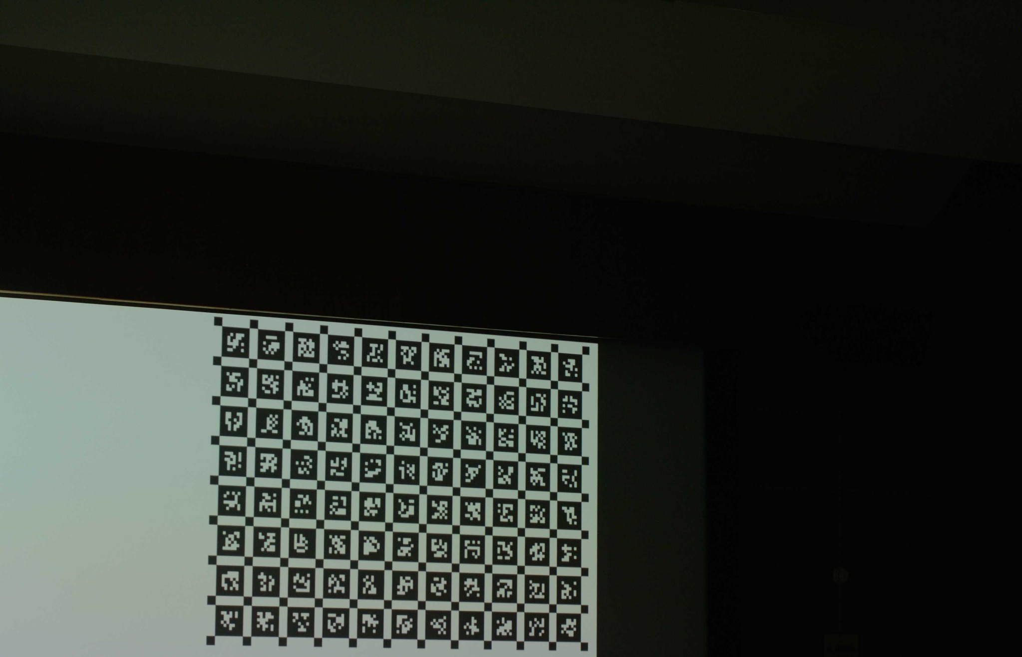
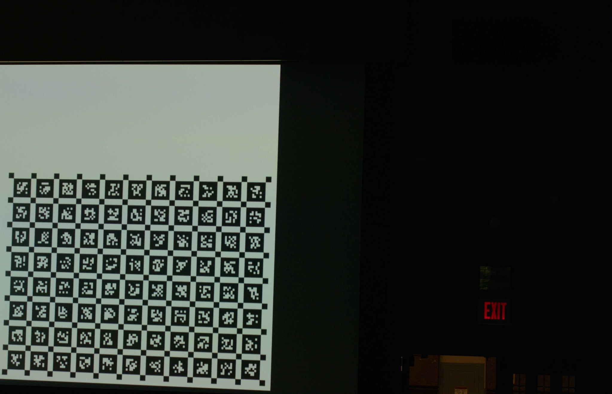
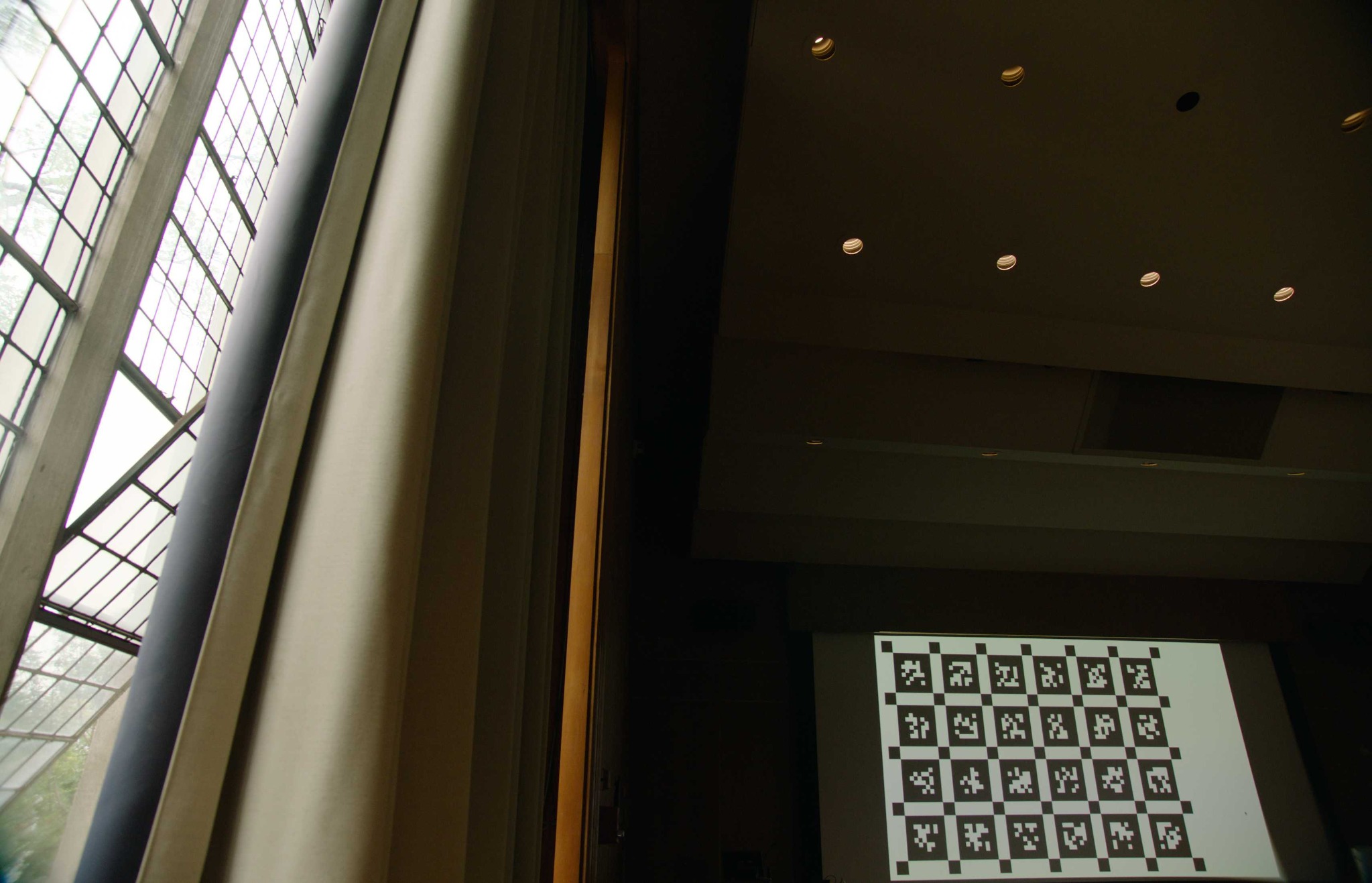
For each lens, we perform calibration over a grid of LFL and FD settings. Each experiment estimates the radial-tangential camera parameters fx, fy, cx, cy, k1, k2, p1, and p2. These discrete calibration results populate the lens-specific LUT, and we use linear interpolation between neighboring experiments in LFL-FD space.
During benchmark capture, the camera records LFL and FD for every frame. We query the LUT at those per-frame values to recover ground truth camera intrinsics.
To construct InFlux++ Synth, we render procedurally generated scenes with virtual cameras whose intrinsics and pose vary over time. Because we have complete information about the rendering camera, we have access to exact per-frame ground truth camera intrinsics and pose, which can act as supervision for training and finetuning dynamic camera intrinsics prediction models. Procedural generation also gives us access to the underlying scene geometry, and we release ground truth depth and surface normals for a subset of InFlux++ Synth.
We build InFlux++ Synth on Infinigen, a procedural scene generator and renderer, to obtain photorealistic and diverse indoor and nature scenes. Infinigen varies lighting, materials, and scene composition through procedural generation, layout optimization, and tuned parameter distributions without manual scene design. Some scenes also contain procedurally generated dynamic objects, such as birds, fish, reptiles, and falling leaves. Because Infinigen renders through Blender, we have access to complete ground truth camera and scene state that would otherwise be difficult to record in the real world.
For natural camera motion, we build on Infinigen's Rapidly-Exploring Random Trees (RRT) camera trajectory generator. After coarse scene geometry is generated, the planner samples collision-free positional waypoints, assigns camera orientations, and connects the resulting pose keyframes using Bezier interpolation. To favor visually informative views with richer geometric structure, we add a surface normal and depth-based criterion that rejects viewpoints dominated by a single coherent surface, such as a blank wall or featureless terrain. We also strengthen orientation resampling and introduce local segment replanning, allowing RRT to recover from locally invalid viewpoints without discarding all previous motion. See the InFlux++ paper for details.
To simulate realistic changes in intrinsics, we vary LFL and LTO continuously over time, analogous to turning the zoom and focus rings on a real camera. We use bounded random walks to define LFL and LTO values at keyframes and apply Bezier interpolation for smooth per-frame variation between keyframes. For indoor scenes, we bound LFL between 8 mm and 100 mm. For nature scenes, we bound LFL between 50 mm and 400 mm. At keyframes, we bound LTO between the nearest and farthest visible scene depths so that the video is in focus at least at certain points in time.
Blender does not provide a direct LFL control. Instead, users specify CFL and LTO independently. This removes the coupling that produces lens breathing, an optical effect in which changing LTO can also change CFL and therefore the camera FOV. For Blender's rendering system, which uses a thin lens model, these quantities are coupled by the following equation:
Using the thin lens equation, we parameterize each frame by LFL and LTO and compute the resulting CFL. This restores lens breathing in the rendered video: even with fixed LFL, changing LTO changes CFL and the camera FOV. Blender then renders the corresponding depth-of-field variation.
Infinigen renders are undistorted by default. When finetuning models with InFlux++ Synth, we apply lens distortion as a data augmentation step. We release a data loader that loads RGB frames and camera metadata and applies configurable radial distortion and optional tangential terms during training. The source renders remain undistorted, so this augmentation can be changed or disabled for a particular experiment.